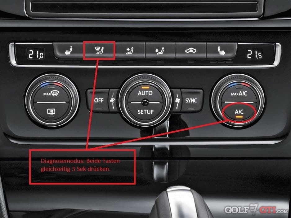
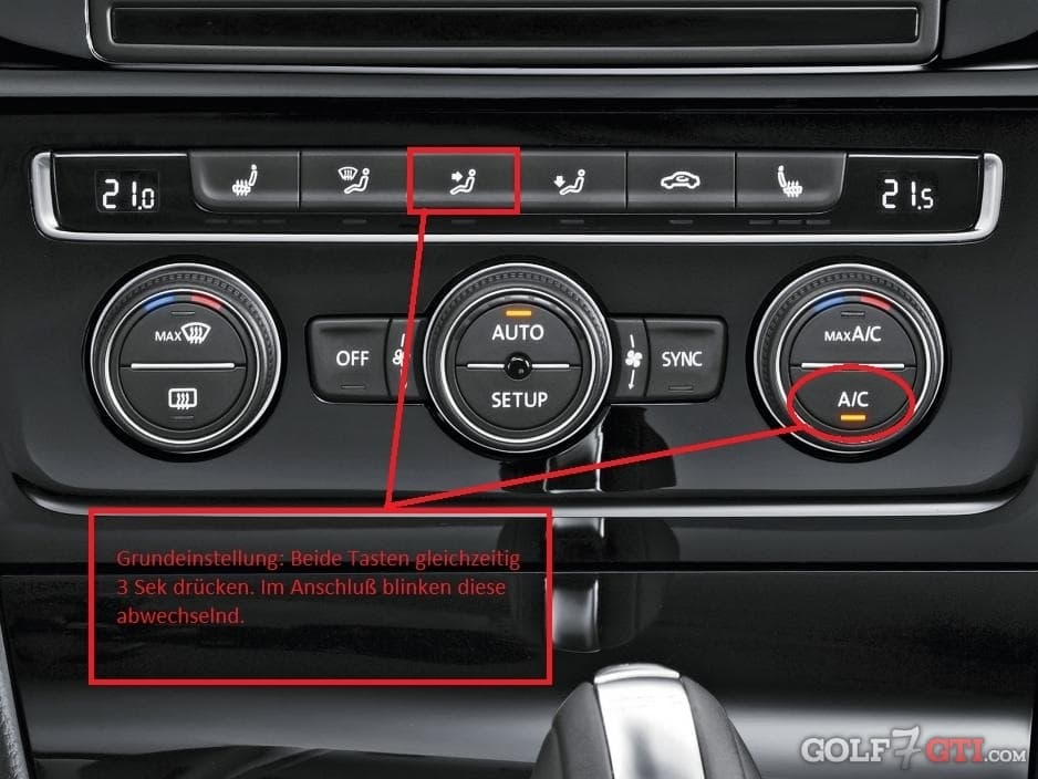
Aus einem englischen Passatforum vom B6:
| 0 – 0 Program number |
Digital 064 |
| 0 – 1 ERL Left |
Digital 064 |
| 0 – 2 ERL Right |
Digital 063 |
| 0 – 3 Point being used |
Digital 000 |
| 0 – 4 Re-circulating Automatic |
Digital 000 |
| 0 – 5 Stationary Heating Active |
Digital 00 |
| 0 – 6 Air Quality (7 = Fresh Air) |
Digital – |
| 0 – 7 Derived |
Digital 03 |
| 0 8 Country Acronym |
Digital 00 |
| 0 – 9 Sensor Zone Head |
°C |
|
|
| UIF |
|
| 1 – 0 Internal Temperature |
°C 28.2 |
| 1 – 1 External Temperature |
°C 27.8 |
| 1 – 4 Uif-Sonnenint? |
Digital 00.0 |
| 1 – 5 Sun Intensity Corrected |
°C 00.0 |
| 1 – 6 Correttore? Dinamico? |
°C 00.8 |
| 1 – 7 Correttore? ricircolo? |
°C 00.0 |
| 1 – 8 correttore? termico? |
°C 00.0 |
|
|
| Sun Intensity Sensor Left |
|
| 2 – 0 Sun Intensity Not Corrected |
W/m2 00 0 |
| 2 – 1 Sun Intensity Corrected |
W/m2 00 0 |
| 2 – 2 Fan Correction |
W/m2 00 0 |
| 2 – 3 Value |
Digital 10 3 |
|
|
| Sun Intensity Sensor Right |
|
| 3 – 0 Sun Intensity Not Corrected |
W/m2 00 0 |
| 3 – 1 Sun Intensity Corrected |
W/m2 00 0 |
| 3 – 2 Fan Correction |
W/m2 00 0 |
| 3 – 3 Value |
Digital 10 0 |
|
|
| 4. External Temperature |
|
| 4 – 0 Temperature External |
°C 20.5 |
| 4 – 2 Temperature Intake |
°C 63.5 |
|
|
| 5. Temperature Left Setpoint |
|
| 5 – 0 Temperature Output |
°C 9.6 |
| 5 – 2 Regulator Setting |
(1/2%) 00 0 |
| 5 – 3 Pi-Stell-Max? |
(1/2%) 10 0 |
| 5 – 4 Defrost |
Digital 00 0 |
|
|
| 6. Temperature Left Actual |
|
| 6 – 0 Temperature |
°C 21.0 |
| 6 – 1 Footwell |
°C 34.6 |
| 6 – 2 Vents |
°C 21.0 |
|
|
| 7. Temperature Right Setpoint |
|
| 7 – 0 Temperature Output |
°C 10.0 |
| 7 – 2 Regulator Setting |
(1/2%) 00 0 |
| 7 – 3 Pi-Stell-Max? |
(1/2%) 10 0 |
| 7 – 4 Defrost Digital |
00 0 |
|
|
| 8. Temperature Right Actual |
|
| 8 – 0 Temperature |
°C 22.3 |
| 8 – 1 Footwell |
°C 28.6 |
| 8 – 2 Vents |
°C 22.6 |
|
|
| 9 – 0 Evaporator temperature |
°C 00.0 |
| 9 – 2 Evaporator value settings |
5mA/Dig 00 0 |
| 9 – 3 Sensor Sight |
0 |
|
|
| 10 – 0 Evaporator Temperature |
°C 23 |
|
|
|
|
|
|
| 11. AC Compressor |
|
| 11 – 0 Power setpoint |
mA 00.0 |
| 11 – 1 Power actual |
mA 00.0 |
| 11 – 2 Power maximum |
mA 00.0 |
| 11 – 4 Power offset compressor |
9.1 |
| 11 – 5 Power value |
Digital 45.2 |
| 11 – 6 Compressor code |
6 |
|
|
| 12. Climate Control Fan |
|
| 12 – 1 Manual regulation |
0 |
| 12 – 2 Code anomaly |
0 |
| 12 – 3 Reduction impeller |
V 00 |
| 12 – 4 Impeller offset |
0.1V 00 |
|
|
| 13. Temperature Air Vent Left |
|
| 13 – 0 Setpoint value |
% 00.0 |
| 13 – 1 Setpoint temperature |
Digital 02 9 |
| 13 – 2 Actual Temperature |
Digital 03 3 |
| 13 – 3 Maximum Temperature |
Digital 23 0 |
| 13 – 4 Minimum Temperature |
Digital 03 3 |
|
|
| 14. Temperature Air Vent Right |
|
| 14 – 0 Setpoint value |
% 00.0 |
| 14 – 1 Setpoint temperature |
Digital 02 1 |
| 14 – 2 Actual Temperature |
Digital 02 5 |
| 14 – 3 Maximum Temperature |
Digital 22 1 |
| 14 – 4 Minimum Temperature |
Digital 02 5 |
|
|
| 15. Temperature Air Vent Diffuser |
|
| 15 – 0 Setpoint value |
% 95.0 |
| 15 – 1 Setpoint temperature |
Digital 22 0 |
| 15 – 2 Actual Temperature |
Digital 22 1 |
| 15 – 3 Maximum Temperature |
Digital 23 1 |
| 15 – 4 Minimum Temperature |
Digital 02 6 |
|
|
| 16. Temperature Air Vent Defrost |
|
| 16 – 0 Setpoint Value |
% 08.0 |
| 16 – 1 Setpoint temperature |
Digital 04 8 |
| 16 – 2 Actual Temperature |
Digital 04 8 |
| 16 – 3 Maximum Temperature |
Digital 22.5 |
| 16 – 4 Minimum Temperature |
Digital 03 3 |
|
|
| 17 – 0 Setpoint Value |
% 00.0 |
| 17 – 1 Setpoint temperature |
Digital 04 4 |
| 17 – 2 Actual Temperature |
Digital 04 8 |
| 17 – 3 Maximum Temperature |
Digital 20 8 |
| 17 – 4 Minimum Temperature |
Digital 04 8 |
|
|
| 18. Temperature External Air |
|
| 18 – 1 Setpoint Temperature |
Digital 23.6 |
| 18 – 2 Actual Temperature |
Digital 23 2 |
| 18 – 3 Maximum Temperature |
Digital 23 1 |
| 18 – 4 Minimum Temperature |
Digital 02 9 |
|
|
| 19. Engine Data |
|
| 19 – 0 Vehicle Speed (kph) |
kph 00 |
| 19 – 1 Vehicle Speed (mph) |
mph 00 |
| 19 – 3 Engine speed |
RPM 00 |
| 19 – 4 AC compress speed |
RPM 00 |
|
|
| 20. CanBus Data |
|
| 20 – 0 Additional Heating |
1=on 00 |
| 20 – 1 PTC Confirmation |
1=on 00 |
| 20 – 2 Effective Power PTC |
A 00 |
| 20 – 3 Air requested from external |
% 00 |
|
|
| 21. Air Distribution |
|
| 21 – 0 Defrost |
% 08.0 |
| 21 – 2 Feet |
% 00.0 |
| 21 – 3 Air Vent Diffuser |
% 10.0 |
| 21 – 4 Re-circulated |
% 00.0 |
|
|
| 22. Time |
|
| 22 – 0 Engine Off Time |
minutes 00.0 |
| 22 – 1 Engine Operating Time |
seconds 00.0 |
| 22 – 3 ? |
00 0 |
| 22 – 4 ? |
00 0 |
| 22 – 5 ? |
28 7 |
|
|
| 23. Special Channel |
|
| 23 – 0 Inner Lighting Sensor |
Digital 00 |
| 23 – 1 Air Quality Sensor |
– |
|
|
| 24. Software Version |
|
| 24 – 0 Development State |
01 0 |
| 24 – 1 Software Version |
22 1 |
| 24 – 2 Type of Software |
00 0 |
| 24 – 4 Version K Matrix |
28 9 |
| 24 – 5 EEP – Test flags |
80 h |
[tr height=32]
[td height=32]1 – 2 Temperature Piastrine in Platinum?[/td]
[td]°C 28.2[/td]
[/tr]
[tr height=32]
[td height=32]1 – 3 Corretor Piastrine in Platinum[/td]
[td]°C 00.1[/td]
[/tr]
[tr height=32]
[td height=32]1 – 9 Compensazione accensione UIF?[/td]
[td]°C 00.1[/td]
[/tr]
[tr height=32]
[td height=32]4 – 1 Temperature External CANBUS[/td]
[td]°C 27.5[/td]
[/tr]
[tr height=32]
[td height=32]5 – 1 Diff. b/w temp & temp setpoint[/td]
[td]°C –11.3[/td]
[/tr]
[tr height=32]
[td height=32]7 – 1 Diff. b/w temp & temp. setpoint [/td]
[td]°C –12.0 [/td]
[/tr]
[tr height=32]
[td height=32]9. Evaporator Temperature Setpoint [/td]
[td] [/td]
[/tr]
[tr height=32]
[td height=32]9 – 1 Diff. b/w temp & temp setpoint [/td]
[td]°C 00.0[/td]
[/tr]
[tr height=32]
[td height=32]10. Evaporator Temperature Actual [/td]
[td] [/td]
[/tr]
[tr height=44]
[td height=44] [/td]
[td](around 30 - 35°C acceptable)[/td]
[/tr]
[tr height=32]
[td height=32] 10 – 1 Liquid refrigerant pressure[/td]
[td]bar 7.4[/td]
[/tr]
[tr height=92]
[td height=92][/td]
[td](Reading from morning cold start was 3.2bar, after
20min run hot weather 9.6bar)[/td]
[/tr]
[tr height=32]
[td height=32] 10 – 2 Liquid refrigerant temperature[/td]
[td]°C 20 0[/td]
[/tr]
[tr height=32]
[td height=32]11 – 3 Compressor PWM[/td]
[td]Digital (0-200) 00 0[/td]
[/tr]
[tr height=32]
[td height=32]12 – 0 Fan Setpoint[/td]
[td]Voltage V 00.0[/td]
[/tr]
[tr height=32]
[td height=32]17. Temperature Internal Recirculation [/td]
[td] [/td]
[/tr]
[tr height=32]
[td height=32]18 – 0 ?[/td]
[td]Flashing 00.0 to 1[/td]
[/tr]
[tr height=32]
[td height=32]19 – 2 Engine (Coolant) Temperature[/td]
[td]°C 79[/td]
[/tr]
[tr height=32]
[td height=32]20 – 4 External air percentage cooler[/td]
[td]% 10[/td]
[/tr]
[tr height=32]
[td height=32]20 – 5 Performance heating[/td]
[td]1=no external provision 01[/td]
[/tr]
[tr height=32]
[td height=32]21 – 1 Face[/td]
[td]% 00.0 flashing to 1[/td]
[/tr]
[tr height=32]
[td height=32]21 – 5 Air Sensor[/td]
[td]% 00.0 flashing to 1[/td]
[/tr]
[tr height=32]
[td height=32]22 – 2 Operating Time with Ignition On[/td]
[td]seconds 25 5[/td]
[/tr]
[tr height=32]
[td height=32]24 – 3 Keep Frozen 0/1 – Diagnosis[/td]
[td]0[/td]
[/tr]
